 |
Sometimes the self-capacitance of the large resistor in a resistive
divider can cause an unwanted passing of high frequencies. This is
often corrected with an added capacitor across the smaller resistor.
But, this can also be corrected numerically:
 |
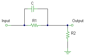
This is the resistive divider with unwanted capacitance, C
|
|
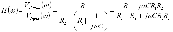
Using similar analysis as with the RC
filters, one derives this transfer function, H, |
|
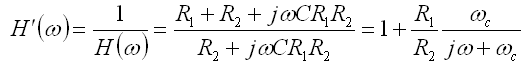
The correction, H', is just the inverse of H, |
|
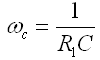
where,
|
|
So, the corrected output is just the original output plus resistor
ratio times the original signal through a low pass filter. Note
that the low pass filter is easily
implemented
numerically. |
|
