Goto: Coaxial Section Output Format Notes
![]()
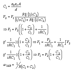
Equation
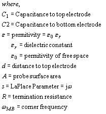
Parameters
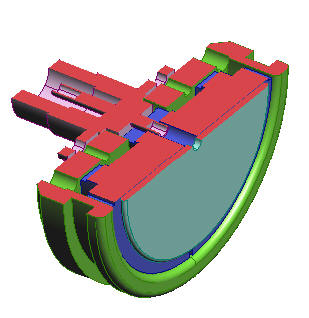
Diagram
![]()
![]()
| Select Format: | Scientific | Engineering | Fixed |
![]()
| If you know dV/dt then enter 1 second for dt and put dV/dt in for dV1 with volt units (as done for the default values). | |
| The Vdot probe is essentially a high pass RC filter with a corner frequency equal to (1/R(C1+C2)) as shown in the bode plot below. | |
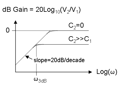 | |
| Care must be taken to ensure that the 3dB point is much higher in frequency than the range of interest. | |
| In most cases, C2>>C1 so that the 3dB frequency is just 1/RC2 | |
| The phase is +90 degrees for low frequencies, +45 at the 3dB point, and 0 at high frequencies. | |
| For frequencies above the 3dB point, the probe acts as a capacitive divider. | |
| The values above are from the design of a typical Vdot probe for Saturn with a center conductor voltage rising to ~800 kV in about 100 ns. The peak dV/dt was estimated from a circuit code. C2 was calculated from a field plotting code. The actual geometry is cylindrical, but the ID is ~6" and OD is ~12" so the approximate planar gap is 6". The probe is placed in a recess in the outer conductor so the surface is flush. The probe is just a 1.8" diameter disk held in a metal cup with plastic support. The output is through an N connector with center pin attached to the disk as shown below: | |
|
| |
| Usually, you'll want the peak output large enough to overcome noise, but
much less than the breakdown strength of the connectors. Also, the 3dB
point is usually desired to be >500 MHz (the bandwidth of a lot of the
scopes).
|
Copyright ©2006 Raymond J. Allen